The Maintenance Manager's Playbook: Your Definitive 2025 Guide to Predictive Maintenance for Screw Compressors
Sep 13, 2025
predictive maintenance for screw compressors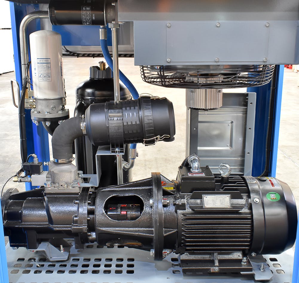
The constant, reassuring hum of a rotary screw compressor is the heartbeat of your facility. It’s a sound that signifies productivity, power, and progress. But for a Maintenance Manager or Reliability Engineer, it’s also a sound that carries an undercurrent of anxiety. What happens when that hum changes? Or worse, when it stops altogether?
Unplanned compressor downtime isn't just an inconvenience; it's a catastrophic failure that can bring an entire production line to a grinding halt. The costs mount with every passing minute—lost revenue, idle labor, expedited shipping for parts, and the frantic scramble of reactive maintenance. For years, the best-practice solution was preventive maintenance (PM): scheduled overhauls, oil changes, and component replacements based on calendar dates or run-hours.
But in 2025, preventive maintenance is no longer enough. It's an inefficient, often wasteful approach. You might replace a perfectly good bearing just because the manual says so, or worse, a bearing could fail catastrophically weeks before its scheduled replacement.
This is where predictive maintenance (PdM) changes the game.
Predictive maintenance isn't about guessing; it's about listening to your equipment with advanced tools and acting on data-driven insights. It’s about shifting from a schedule-based "just-in-case" model to a condition-based "just-in-time" strategy. This playbook is designed for you—the technical professional on the front lines. We'll move beyond high-level theory and give you a practical, step-by-step guide to implementing a world-class predictive maintenance program for your most critical screw compressors.
Understanding Screw Compressor Failure Modes: The "Why" Behind PdM
To effectively predict failures, you must first deeply understand how and why screw compressors fail. A screw compressor is a complex piece of rotating equipment, but its failures are often predictable if you know what to look for. Let's dissect the most common failure modes.
Airend Failure: The Heart of the Problem
The airend, or air end, is the core of the compressor where two intermeshing helical rotors compress the air. It's the most expensive component and the source of the most catastrophic failures.
Bearing Failure
This is, without a doubt, the number one cause of airend failure. The rotors are supported by a combination of radial and thrust bearings that operate under extreme loads and high speeds. When they fail, the result is often rotor-to-rotor or rotor-to-housing contact, which effectively destroys the airend.
- Root Causes: Lubrication issues (contamination, degradation, low levels), excessive load, misalignment, improper installation, or simply reaching the end of their fatigue life.
- Predictive Clues: High-frequency vibrations, changes in oil analysis wear metals (iron, chromium), and rising temperature signatures are all early indicators. We'll cover the specific techniques to detect these clues in the next section.
Rotor Contact and Wear
When the precision clearance between the male and female rotors (or between the rotors and the housing) is compromised, they make contact. This is almost always a secondary failure resulting from a primary issue like bearing failure. The resulting metal-on-metal grinding generates significant debris, contaminating the entire oil system and leading to a full airend rebuild or replacement.
- Root Causes: Catastrophic bearing failure, severe oil contamination, or a "liquid slug" (sucking in oil or condensate).
- Predictive Clues: A sudden, significant spike in vibration and audible noise are the most immediate indicators. A sharp increase in large metallic particles in the oil is also a tell-tale sign.
Seal Failure
Shaft seals prevent the high-pressure oil from leaking out of the airend. A failing seal can lead to significant oil loss, housekeeping issues, and potential oil starvation for the bearings if left unchecked.
- Root Causes: Normal wear and tear, contaminated oil abrading the seal surface, or excessive shaft vibration.
- Predictive Clues: Visual oil leaks are a late-stage indicator. An ultrasonic detector can often "hear" the high-frequency hiss of a leak long before it's visible.
Motor and Drive System Failures
The airend doesn't work in isolation. The electric motor and drive system that power it are also common points of failure.
- Motor Bearing Failure: Just like the airend, motor bearings are susceptible to lubrication and wear issues.
- Coupling Misalignment: In direct-drive compressors, the coupling between the motor and the airend is critical. Misalignment puts immense stress on both the motor and airend bearings, drastically shortening their lifespan.
- Belt/Pulley Issues: For belt-driven compressors, worn belts, improper tension (too tight or too loose), and pulley misalignment can cause vibration and premature bearing failure.
Lubrication System Failures
The oil in a rotary screw compressor does more than just lubricate. It also cools the compression process, seals the clearances between the rotors, and carries away contaminants. The health of your oil is the health of your compressor.
- Oil Degradation: Over time, heat and oxidation break down the oil, reducing its viscosity and ability to lubricate effectively. This process also forms varnish and sludge that can clog oil lines and coolers.
- Contamination: Water, dirt, and wear particles contaminate the oil, turning it into a liquid grinding paste that accelerates wear on all moving parts.
- Clogged Filters and Coolers: If the oil filter becomes clogged, a bypass valve will open, allowing unfiltered, contaminated oil to circulate. A clogged oil cooler will cause the compressor's operating temperature to rise, accelerating oil degradation and potentially triggering high-temperature shutdowns.
The Predictive Maintenance Toolkit: Your Arsenal of Sensors and Techniques
Now that we understand what can go wrong, let's explore the technologies that allow us to see these failures coming. A robust PdM program uses a multi-faceted approach, as no single technology can detect every failure mode.
Vibration Analysis: Listening to the Machine's Heartbeat
Vibration analysis is the cornerstone of predictive maintenance for any rotating equipment, and screw compressors are no exception. Every rotating component has a unique vibration signature when it's healthy. As faults develop, they introduce new frequencies and change the amplitude of existing ones.
- What It Detects:
- Bearing Faults: The most valuable application. Vibration analysis can detect microscopic defects on the inner race, outer race, balls/rollers, and cage of a bearing months before they become critical. It can even differentiate between the specific failing component.
- Misalignment: Detects angular or parallel misalignment between the motor and airend shafts.
- Unbalance: Identifies issues with rotating components like cooling fans or pulleys.
- Gear Mesh Issues: In gear-driven compressors, it can detect worn or damaged gear teeth.
- Technical Details: Analysts use a technique called Fast Fourier Transform (FFT) to break down the complex vibration signal into its individual frequencies. For example, a fault on the outer race of a bearing will show up at a specific, calculable frequency known as the Ball Pass Frequency Outer race (BPFO).
- Implementation: Piezoelectric accelerometers are mounted at key locations, primarily on the drive and non-drive end bearing housings of both the motor and the airend. Data can be collected periodically with a handheld analyzer or continuously with permanently mounted wireless sensors. For an in-depth look at this technology, exploring solutions for predictive maintenance for bearings is a great next step.
Oil Analysis: The Compressor's Blood Test
If vibration analysis is like an EKG for your compressor, oil analysis is the equivalent of a comprehensive blood test. A small sample of oil, when analyzed by a lab, provides a wealth of information about the health of both the lubricant and the machine itself.
- Key Tests & What They Reveal:
- Elemental Spectroscopy (ICP): Detects the presence of microscopic wear metals in parts per million (ppm). An increase in iron points to gear or bearing wear, while copper might indicate bearing cage or cooler corrosion.
- Particle Count: Measures the overall cleanliness of the oil using the ISO 4406 standard. A rising particle count indicates that the filtration system is not keeping up or that a severe wear event is in progress.
- Viscosity: Measures the oil's resistance to flow. A significant drop or increase in viscosity indicates the oil is breaking down or has been contaminated.
- Total Acid Number (TAN): Measures the level of acidic byproducts from oxidation. A high TAN indicates the oil has degraded and needs to be changed.
- Water Content: Detects the presence of water, a major contaminant that promotes rust and oil degradation.
- Implementation: The key to effective oil analysis is consistency. Samples should be taken from the same point (ideally a live-zone sample port, mid-stream) while the machine is running at normal operating temperature. Trending the results over time is far more valuable than any single report. According to an article from Maintenance World, proper sampling technique is paramount for accurate results.
Thermal Imaging (Infrared Thermography): Seeing the Heat
Infrared cameras translate surface heat into a visible image, allowing you to spot thermal anomalies that are often precursors to failure.
- What It Detects:
- Overheating Bearings: A failing bearing will generate excess heat due to friction.
- Clogged Coolers: You can visually see hot spots or uneven temperature distribution across an oil or air cooler, indicating blockages.
- Electrical Faults: Loose connections in the motor starter, disconnect, or VFD create resistance and heat up long before they fail.
- Coupling Issues: A misaligned or failing coupling can generate significant heat.
- Implementation: Thermography is a non-contact technology, making it safe and easy to perform while the compressor is running. The key is to establish a thermal baseline of the equipment under normal load and then look for deviations during routine inspections.
Ultrasonic Analysis: Hearing Beyond Human Limits
Our ears can't hear the high-frequency sounds generated by certain mechanical and electrical faults, but ultrasonic detectors can. This technology is an excellent complement to vibration analysis.
- What It Detects:
- Early-Stage Bearing Failure: Before a bearing defect is large enough to create significant low-frequency vibration, it generates high-frequency ultrasonic noise. This is often the very first sign of a problem, particularly related to a lack of lubrication.
- Air/Gas Leaks: The turbulent flow of air escaping from a pipe fitting, hose, or seal generates a distinct ultrasonic signature, making it easy to pinpoint costly leaks in your compressed air system.
- Electrical Faults: Arcing, tracking, and corona in high-voltage electrical cabinets produce ultrasound.
The Implementation Playbook: A Step-by-Step Guide to Launching Your PdM Program
Knowing the technologies is one thing; successfully implementing a program is another. Follow this structured, five-step playbook to move from theory to the shop floor.
Step 1: Asset Criticality Analysis & Pilot Program Selection
You can't—and shouldn't—try to implement PdM on every piece of equipment at once. The first step is to identify your most critical compressors.
- How to Rank: Create a simple matrix. On one axis, rate the "Consequence of Failure" (e.g., 1-10, where 10 means a full plant shutdown). On the other axis, rate the "Likelihood of Failure" based on age, history, and operating conditions. The compressors in the top-right quadrant (high consequence, high likelihood) are your prime candidates.
- Start Small: Select 2-3 of your most critical compressors for a pilot program. This allows you to prove the concept, refine your processes, and demonstrate ROI before seeking a larger investment. This focused approach minimizes initial risk and builds momentum for a full-scale rollout.
Step 2: Defining Failure Modes and Selecting Technologies
For your pilot compressors, formally map the likely failure modes (from our list above) to the PdM technologies you'll use to detect them. This ensures you have complete coverage.
Example FMECA-to-PdM Mapping Table:
| Component | Potential Failure Mode | Primary PdM Technology | Secondary PdM Tech | Frequency |
|---|---|---|---|---|
| Airend | Thrust Bearing Wear | Vibration Analysis | Oil Analysis | Monthly |
| Airend | Rotor Seal Leak | Visual Inspection | Ultrasonic Analysis | Weekly |
| Motor | Drive End Bearing Fault | Vibration Analysis | Thermography | Monthly |
| Lubrication | Oil Degradation (Oxidation) | Oil Analysis (TAN) | Temperature Monitoring | Quarterly |
| Drive System | Coupling Misalignment | Vibration Analysis | Laser Alignment (Corrective) | Monthly |
| Electrical | Loose Starter Connection | Thermography | Visual Inspection | Quarterly |
Step 3: Establishing a Baseline
This is the most critical step in the entire process. You cannot detect an abnormal condition if you do not know what normal looks like.
- The Process: Once your sensors are installed or your data collection routes are defined, you must collect data while the compressor is running in a known healthy state under typical operating loads.
- Data Collection Period: Don't rely on a single reading. Collect data over a period of several weeks to capture the natural variability in your process.
- Document Everything: Record the operating parameters alongside each data point: load percentage, discharge pressure, ambient temperature, etc. This context is vital for accurate analysis. For example, a vibration reading might be higher at full load than at 50% load—this isn't an alarm, it's a normal operating characteristic.
Step 4: Setting Alarms and Thresholds
With a solid baseline established, you can now define the limits that will trigger an action.
- Static Alarms: You can start with industry standards, like the ISO 10816-3 standard for machinery vibration levels. These provide general guidelines for different classes of machines.
- Statistical Alarms (The Better Way): A far more effective method is to use statistical analysis of your own baseline data.
- Alert (Level 1): Set at 2 standard deviations (2σ) above the baseline mean. This is an early warning. It doesn't mean the machine is failing, but it warrants closer investigation.
- Alarm (Level 2): Set at 3 standard deviations (3σ) above the baseline mean. This indicates a significant change. It's time to generate a work order and plan a corrective action.
Step 5: Integrating Data into Your Workflow (The CMMS Role)
Collecting data is useless if it sits in a spreadsheet on someone's laptop. The data must flow seamlessly into your maintenance workflow to trigger action. This is where a modern Computerized Maintenance Management System (CMMS) becomes the brain of your PdM program.
- The Central Hub: A powerful CMMS for predictive maintenance acts as the central repository for all your condition monitoring data.
- Automated Workflows: The real power comes from automation. When a sensor platform detects that a vibration reading has crossed the "Alarm" threshold, it can communicate directly with the CMMS. The CMMS then automatically generates a work order, assigns it to the right technician, includes the relevant data (the vibration spectrum), and attaches the standard procedure for investigating a high-vibration alarm.
- Seamless Connectivity: This level of automation relies on robust integrations between your sensor hardware, your analytics platform, and your CMMS. This connected ecosystem eliminates manual data entry, reduces human error, and ensures that no alert ever falls through the cracks.
Step 6: Analysis, Action, and Refinement
The final step is a continuous loop of improvement.
- Analysis: When an alarm is triggered, a trained analyst (whether in-house or a third-party service) must interpret the data to diagnose the specific fault. Is the high vibration a bearing fault or misalignment? Is the high particle count from dirt ingress or an internal failure?
- Action: Based on the diagnosis, a corrective maintenance plan is created and executed. The beauty of PdM is that this is now planned work, not an emergency. You can schedule the repair for a planned outage, order the parts ahead of time, and ensure the right resources are available.
- Refinement: After the repair, conduct a root cause analysis (RCA). Did the PdM program catch the failure as expected? Could the alarm limits be refined for even earlier detection? Feed these lessons back into your program to make it smarter and more effective over time.
Building the Business Case: Calculating the ROI of Compressor PdM
To get budget approval, you need to speak the language of management: money. A predictive maintenance program is not a cost center; it's a profit center disguised as a maintenance strategy.
The "Cost of Inaction" - Quantifying Downtime
First, calculate the true cost of a single unplanned compressor failure. Be thorough.
Cost of Downtime = (Lost Production Revenue) + (Reactive Repair Costs) + (Wasted Labor Costs)
- Lost Production Revenue: How much revenue does your plant generate per hour? If a failed compressor stops that production, what is the financial impact?
- Example: A plastic molding facility generates $15,000/hour in revenue. The main compressor fails, stopping all 20 molding machines. A 6-hour outage costs $90,000 in lost revenue alone.
- Reactive Repair Costs: This includes the cost of the replacement airend or motor, plus expedited shipping fees, and potential overtime pay for technicians. A rush-ordered airend can cost 25-50% more than one ordered with standard lead time.
- Wasted Labor Costs: The cost of all the production operators standing idle while the machine is down.
The Investment: What Does a PdM Program Cost?
Be transparent about the upfront and ongoing costs.
- Hardware: Wireless sensors (vibration, temperature) can range from $300 to $1,000 per unit.
- Software: The analytics platform and CMMS are typically sold as a SaaS subscription, priced per asset or per user.
- Training: Certifying a technician in Level 1 Vibration Analysis can cost $2,000 - $3,000.
- Services: You might opt to use a third-party service for data analysis, which has its own monthly or annual fee.
Calculating Your Potential ROI
Now, let's put it all together in a conservative, real-world scenario.
- Scenario: You implement a PdM pilot program on 2 critical compressors.
- Investment:
- Hardware (8 sensors total for 2 compressors): $6,000
- Software & Platform (1 year): $4,000
- Training (1 technician): $3,000
- Total Year 1 Investment: $13,000
- Gains (Return):
- Avoided Downtime: The program detects an impending airend bearing failure 6 weeks in advance. You schedule the repair during a planned weekend shutdown. You avoid a catastrophic failure that would have caused an 8-hour outage.
- Avoided Lost Revenue: 8 hours x $15,000/hour = $120,000
- Avoided Reactive Costs: Saved $15,000 on an emergency airend rebuild vs. a planned one.
- Reduced PM Costs: You eliminate two "preventive" bearing replacements on healthy machines, saving 16 hours of labor and $2,000 in parts. Labor savings: 16 hours x $75/hr = $1,200. Total = $3,200.
- Total Year 1 Gain: $120,000 + $15,000 + $3,200 = $138,200
- Avoided Downtime: The program detects an impending airend bearing failure 6 weeks in advance. You schedule the repair during a planned weekend shutdown. You avoid a catastrophic failure that would have caused an 8-hour outage.
ROI = (Gain from Investment - Cost of Investment) / Cost of Investment ROI = ($138,200 - $13,000) / $13,000 = 963%
An ROI of over 900% in the first year is not an exaggeration; it's a common reality for well-implemented PdM programs on critical assets.
Advanced Concepts and the Future (2025 and Beyond)
Predictive maintenance is the standard for best-in-class operations today, but technology continues to advance. Staying ahead of the curve means understanding what's next.
From Predictive to Prescriptive Maintenance
The next evolution is already here. While predictive maintenance tells you what will fail and when, prescriptive maintenance tells you what to do about it.
- The Difference:
- Predictive: "The drive-end motor bearing will likely fail in the next 4-6 weeks."
- Prescriptive: "The drive-end motor bearing will likely fail in 4-6 weeks. To safely extend its life until the next planned shutdown in 5 weeks, we recommend reducing the compressor's max load to 85%. The required bearing is part number 6210-2RS. Here is the optimized work order to replace it."
This leap is made possible by combining condition data with operational data (load, pressure, etc.) and feeding it all into AI and machine learning algorithms. These systems can run thousands of simulations to provide optimal recommendations. This is the future of intelligent asset management, and platforms are increasingly offering prescriptive maintenance capabilities.
The Rise of AI and Machine Learning
Artificial intelligence is the engine driving the future of PdM. Instead of relying solely on human analysts to spot trends, AI-powered systems can analyze millions of data points in real-time. They can identify complex patterns and correlations that are invisible to the human eye, leading to even earlier and more accurate fault detection. The true power of AI-powered predictive maintenance lies in its ability to learn and adapt, continuously improving the accuracy of its predictions as it gathers more data from your specific machines.
Stop Reacting, Start Predicting: Take Control of Your Compressed Air System
The days of running your critical compressors until they break are over. The era of wasteful, calendar-based maintenance is fading. The financial and operational risks are simply too high in today's competitive landscape.
Implementing a predictive maintenance program for your screw compressors is a strategic imperative. It's a journey that transforms your maintenance department from a reactive cost center into a proactive, data-driven contributor to the bottom line. By understanding your machine's failure modes, deploying the right technologies, and following a structured implementation plan, you can eliminate unplanned downtime, reduce maintenance costs, and extend the life of your most critical assets.
The hum of your compressor should be a sound of confidence, not anxiety. It's time to take control.
Ready to move beyond spreadsheets and reactive fire-fighting? Explore how a dedicated predictive maintenance platform for compressors can provide the tools, insights, and workflow automation you need to build a world-class reliability program.